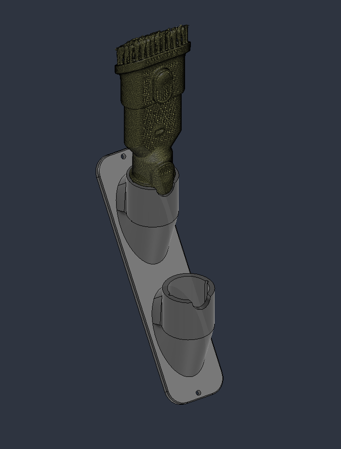
Design study / Reverse engineering / 3D printing
Vacuum Accessory Dock
A custom dock built around an existing accessory connection, using 3D scanning and CAD to move from physical geometry to a functional printed part.
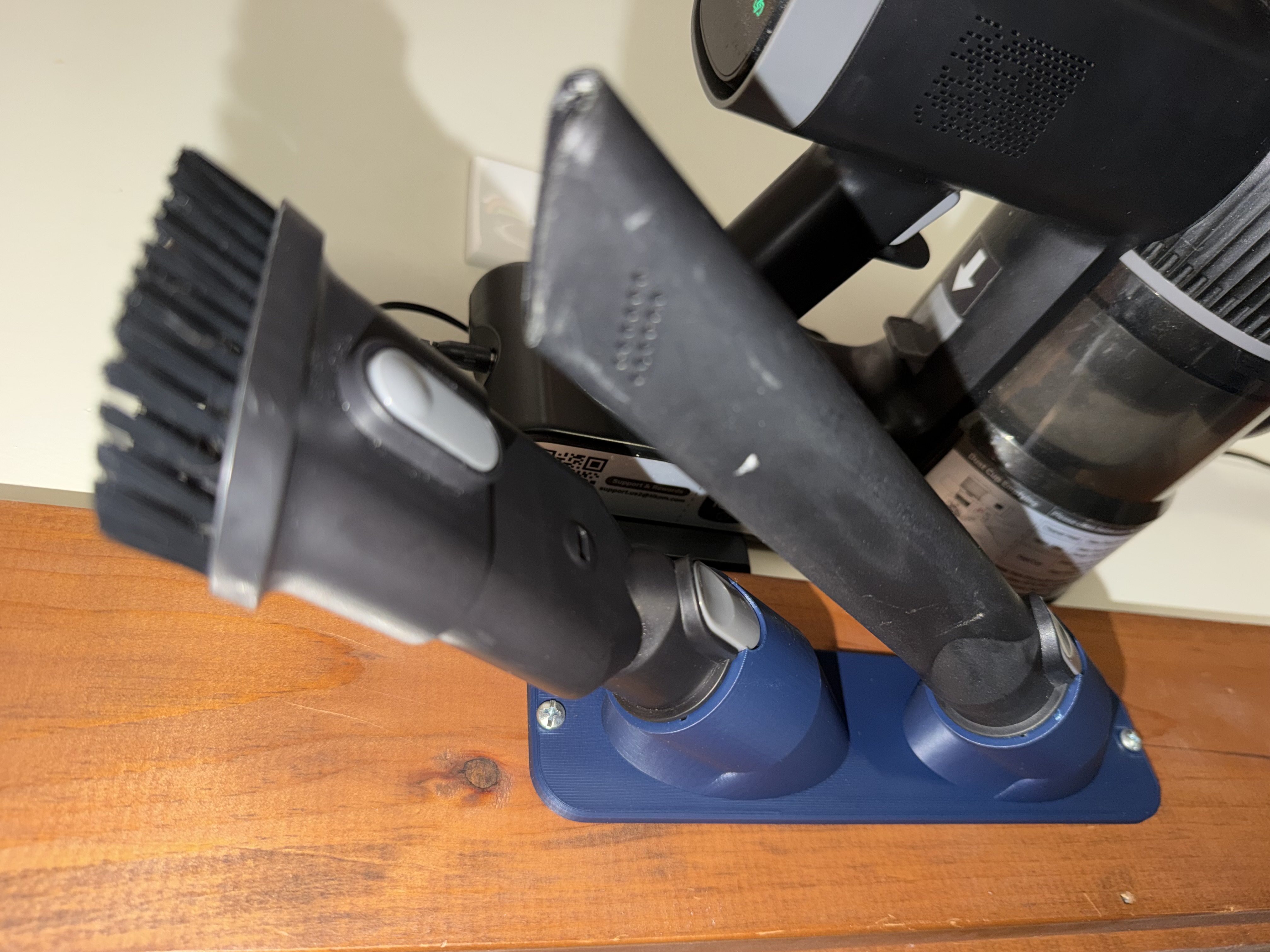
A practical place to start
I wanted a wall-mountable docking system for my vacuum accessories, and a practical project to improve my 3D scanning workflow.
The connection between the accessory and the dock was the focus: capture the existing shape, reconstruct it as editable geometry, and use it to form the receiving socket.
- Process
- 3D scanning, mesh cleanup, reverse engineering, CAD, 3D printing
- Software
- RevoScan, Solid Edge Community Edition, Fusion
- Outcome
- A mounted, two-accessory dock
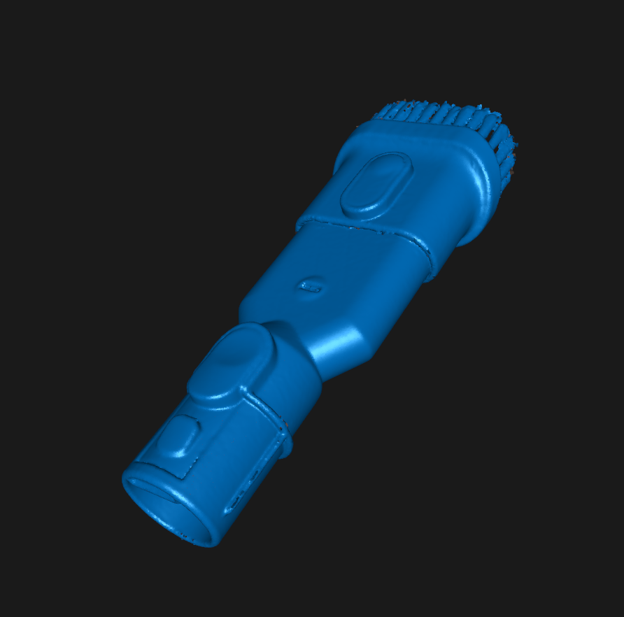
01 / Capture
Scan the mating interface
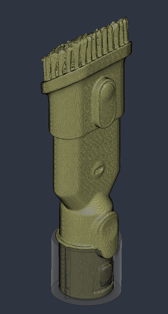
I took multiple scans focused on the accessory’s mating interface. I merged the point clouds, smoothed and simplified the data, and isolated the relevant geometry before creating the final mesh.
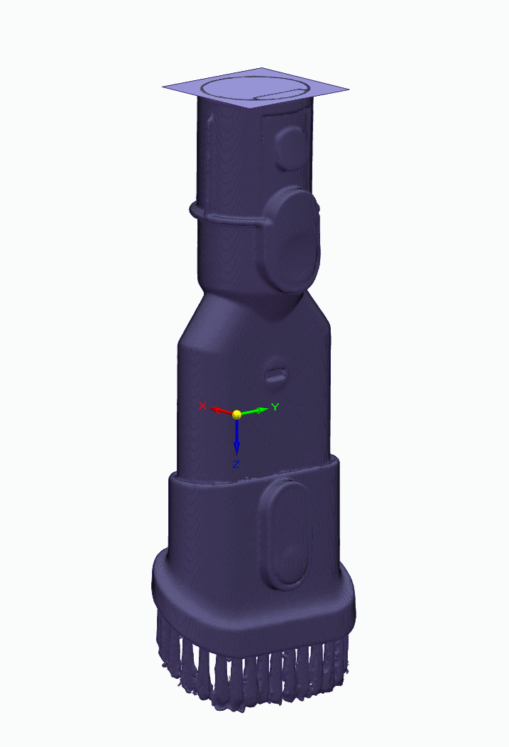
02 / Establish a reference
Create a datum plane
In Solid Edge Community Edition, I used the feature-selection brush to identify a region of the mesh and fit a datum plane as closely as possible. This gave me a geometric reference for the next stage.
03 / Reconstruct
Turn the mesh into editable CAD
I brought the model into Fusion and created multiple mesh sections to reconstruct the mating hardware. These sections helped me work from a mesh reference toward an editable positive model of the connection.
I then used Combine to subtract that positive shape from a solid block, creating the negative geometry of the receiving socket.
04 / Build the dock
Connect the sockets to a mounting plate
Using a loft and basic CAD features, I connected the socket to a wall-mounting structure. I copied and moved the socket geometry, then joined the bodies to create a dock for two accessories.
The finished printed part holds both accessories together beside the vacuum. The project took the interface through the full workflow: scan, reference geometry, editable CAD, and a physical dock.